
How to convert pressure in mass spectrometry
What does a metering valve do?
How does a pressure converter work?
In order to examine a gas mix at total pressure exceeding 1 · 10-4 mbar it is necessary to use pressure converters which will not segregate the gases. Figure 4.7 is used to help explain how such a pressure converter works:
a. Process pressure < 1 mbar: Single-stage pressure converter. Gas is allowed to pass out of the vacuum vessel in molecular flow, through a diaphragm with conductance value L2 and into the “sensor chamber” (with its own high vacuum system). Molecular flow causes segregation but this will be independent of the pressure level. A second diaphragm with molecular flow, located between the sensor chamber and the turbomolecular pump, will compensate for the segregation occurring at L2.
b. Process pressure > 1 mbar: Two-stage pressure converter. Using a small (rotary vane) pump a laminar stream of gas is diverted from the rough vacuum area through a capillary or diaphragm (conductance value L3). Prior to entry into the pump, at a pressure of about 1 mbar, a small part of this flow is again allowed to enter the sensor chamber through the diaphragm with conductance value L2, again as molecular flow.
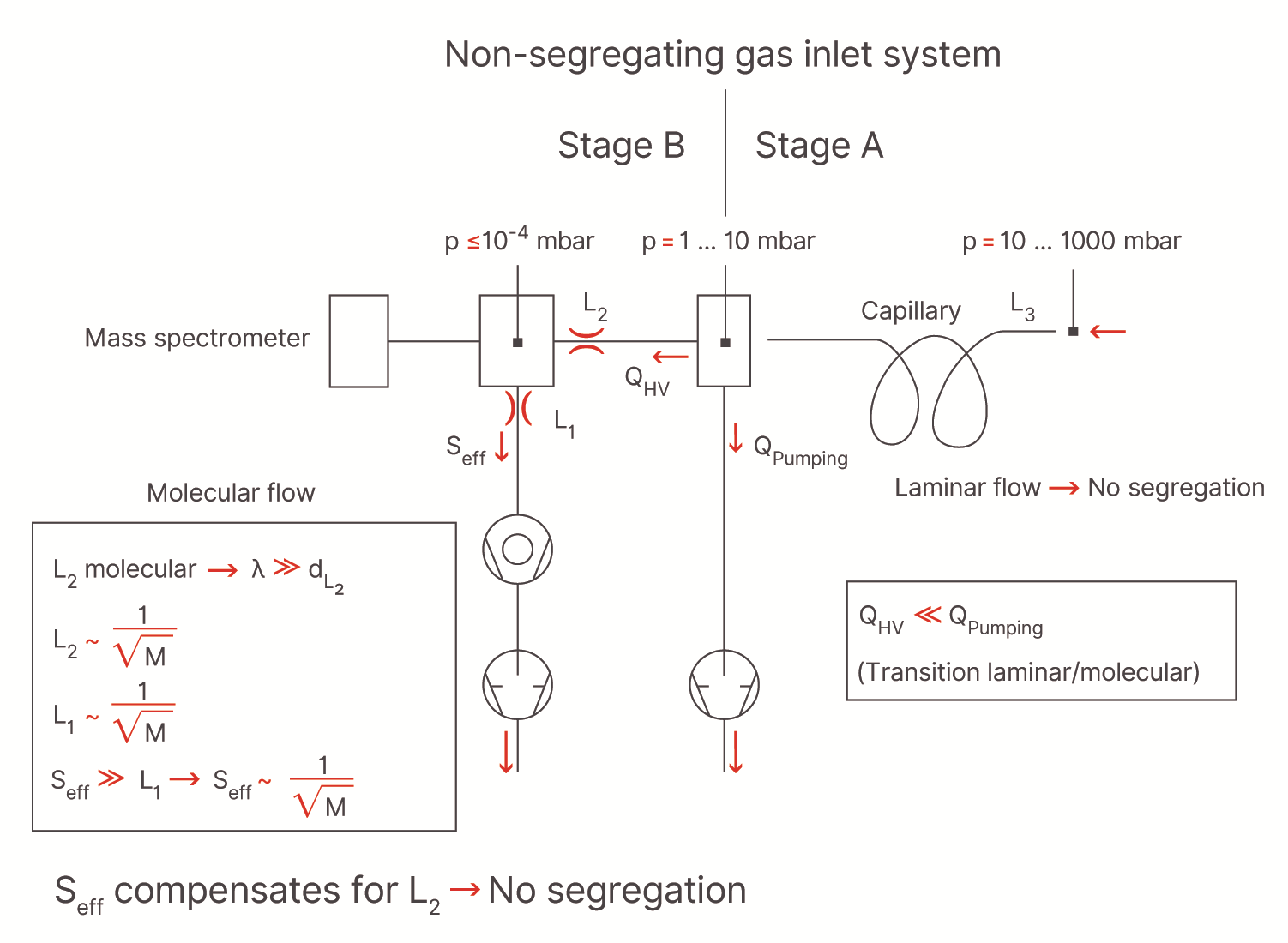
Fig 4.7 Principle of the pressure converter (stage B only in the single-stage version and stages A and B in the two-stage units)
A falsification of the gas composition resulting from adsorption and condensation can be avoided by heating the pressure converter and the capillary.
To evaluate the influence on the gas composition by the measurement unit itself, information on the heating temperature, the materials and surface areas for the metallic, glass and ceramic components will be needed along with specifications on the material and dimensions of the cathode (and ultimately regarding the electron impact energy for the ion source as well).
Closed ion source (CIS)
In order to curb – or avoid entirely – influences which could stem from the sensor chamber or the cathode (e.g. disturbance of the CO-CO2 equilibrium by heating the cathode) a closed ion source (CIS) will be used in many cases.
The CIS is divided into two sections: a cathode chamber where the electrons are emitted, and an impact chamber, where the impact ionization of the gas particles takes place. The two chambers are pumped differentially: the pressure in the cathode chamber comes to about 10-5 mbar, that in the impact room about 10-3 mbar. The gas from the vacuum chamber is allowed to pass into the impact chamber by way of a metal-sealed, bakeable valve (pressure converter, ultrahigh vacuum technology). There high-yield ionization takes place at about 10-3 mbar. The electrons exerting the impact are emitted in the cathode chamber at about 10-5 mbar and pass through small openings from there into the impact chamber. The signal-to-noise ratio (residual gas) via à vis the open ion source will be increased overall by a factor of 10+3 or more. Figure 4.8 shows the fundamental difference between the configurations for open and closed ion sources for a typical application in sputter technology. With the modified design of the CIS compared with the open ion source in regard to both the geometry and the electron energy (open ion source 102 eV, CIS 75 or 35 eV), different fragment distribution patterns may be found where a lower electron energy level is selected. For example, the argon36++ isotope at mass of 18 cannot be detected at electron energy of less than 43.5 eV and can therefore not falsify the detection of H2O+ at mass 18 in the sputter processes using argon as the working gas – processes which are of great importance in industry.
-and-closed-ion-source-(right).tif/_jcr_content/renditions/cq5dam.web.1600.1600.jpeg)
Fig 4.8 Open ion source (left) and closed ion source (right)
Aggressive gas monitor (AGM) working principle
In many cases the process gas to be examined is so aggressive that the cathode would survive for only a short period of time. The AGM uses the property of laminar flow by way of which there is no “reverse” flow of any kind. Controlled with a separate AGM valve, a part of the working gas fed to the processes is introduced as “purging gas”, ahead of the pressure converter, to the TRANSPECTOR; this sets up a flow toward the vacuum chamber. Thus, process gas can reach the TRANSPECTOR only with the AGM valve closed. When the valve is open the TRANSPECTOR sees only pure working gas. Fig. 4.9 shows the AGM principle.
.tif/_jcr_content/renditions/cq5dam.web.1600.1600.jpeg)
Fig 4.9 Principle behind the aggressive gas monitor (AGM)

Fundamentals of Vacuum Technology
Download our e-Book "Fundamentals of Vacuum Technology" to discover vacuum pump essentials and processes.
References
- Vacuum symbols
- Glossary of units
- References and sources
Vacuum symbols
Vacuum symbols
A glossary of symbols commonly used in vacuum technology diagrams as a visual representation of pump types and parts in pumping systems
Glossary of units
Glossary of units
An overview of measurement units used in vacuum technology and what the symbols stand for, as well as the modern equivalents of historical units
References and sources
References and sources
References, sources and further reading related to the fundamental knowledge of vacuum technology
Vacuum symbols
A glossary of symbols commonly used in vacuum technology diagrams as a visual representation of pump types and parts in pumping systems
Glossary of units
An overview of measurement units used in vacuum technology and what the symbols stand for, as well as the modern equivalents of historical units
References and sources
References, sources and further reading related to the fundamental knowledge of vacuum technology
